services | history | projects | project types | more | contact
Zero-stress design℠
Use of stainless steel and zero-stress design℠ produces elegant, stronger, lighter and safer buildings
John Mclean, RA, Architect and Industrial Designer, presented his revolutionary vision for a new architecture to the SSINA members at its Market Development Meeting in Alexandria, Washington, DC, on 10 April 2003.
Mclean’s approach to design uses stainless steel exclusively as the building material of choice. More specifically, stainless steel and water are the principal structural materials, and the basis for his concept of zero-stress design℠. Architectural drawings and models expressed his vision for this revolutionary architectural approach that uses stainless steel to produce an elegant, stronger, lighter and safer building. An additional benefit of the stainless steel zero-stress structure℠ is that the structural elements form the finished face of the entire structure.
Mclean demonstrated the strength of a structure using zero-stress design℠, with a unique test model, and then proceeded to analyze the individual components of the structural model he was proposing.
This new type of building results in a higher strength capacity, than can be realized with carbon steel. Zero-stress design℠, eliminates compressive stress, with the result that the maximum structural strength of stainless steel is always tapped.
The unique characteristics of zero-stress design℠ are:
A stronger and lighter structure that uses
stainless steel’s unique properties to the maximum.
A structure that is inherently fire-resistant.
A structure that is corrosion resistant.
A structure that is resilient to seismic shock.
A structure in which the effects of temperature change can
be controlled to suit the desired design parameters of the project.
Mclean presented a new type of tension bridge, based on zero-stress design℠, capable of great spans; a different kind of tall building, that is efficient and not massive; and a new building type, which he called the “horizontal skyscraper”. The tragic events of September 11th when analyzed reveal that stainless steel, coupled with zero-stress design℠, should be the exclusive building material of the 21st century and not merely a premium material.
The need to reconstruct our infrastructure, worldwide, can prove to be the opportunity of the century. Stainless steel as used in Zero-stress design℠ is the avant-garde in architecture that can launch stainless steel as the building material of the 21st century.
Architecture and
‘Zero-stress’℠ structures
A simple system using water-filled tubes lends itself to industrialized building and to greater spatial benefits and safety.
by John Mclean, RA

Horizontal Skyscraper℠
The principles of zero stressing℠ lend themselves to such applications as this urban housing complex. This horizontal skyscraper℠ is a series of spanning units, each containing about five duplex or triplex residences. This fragmented skyscraper horizontally contrasts with the vertical monolithic office towers. The housing spans (or bridges) are zero-stressed beams or trusses. Each is built on the ground, and then zero-stressed℠ and jacked into position, where it is supported on a zero-stress℠ column system.
A building’s weight is tremendous. Often the heaviest parts do nothing structurally. This is inefficient. If the ratio could be reversed, structural efficiency would be greatly improved. A large building weight is indicative not only of massiveness but of redundant construction. Many types of exterior enclosures or “skins” are as strong as the structure supporting them, and may weigh more. Claddings should be tapped structurally.
If the industrialization of building aims to make construction more affordable, then it means, in addition to mass production methods, the further development of lighter and stronger structures, new materials technology and the integration of building components. Useful materials must be evaluated for their architectural potential. Ways of using glass and plastic materials structurally should be found. Conventional construction materials should be made able to perform at a higher level.
The zero-stress℠ structural system, a design research project proposed here, is intended to reduce the cost of building. The reductions would come from the system’s high structural strength and efficiency, and its receptiveness for integrating building components into the structural system itself.
A zero-stress℠ structure is light. A zero compressive state maximizes the strength of the material used, so that the structure can be considerably less massive.
Zero-stressing℠ extends architectural and spatial concepts. Unlike many structural systems, zero-stress is not based on a special geometric configuration and is therefore widely applicable. The design proposals illustrated are spatially tensile and vibrant.
Zero-stressing℠ may allow us to use materials such as plastics and reinforced or structural glass for structural purposes. Plastic materials have been developed with strength—but not stiffness—approaching that of steel. Consequently, plastic columns and beams have had extremely limited uses. Nevertheless, the structural possibilities of plastics, glass, steel, nickel-stainless steel and reinforced concrete are tremendously extended by zero-stressing℠. A possible spin-off of the zero-stress technology℠ is the further strengthening of materials such as steel. We increase the strength of glass fourfold by tempering it. In a similar manner, by highly pressurizing molten steel and allowing it to cool in a columnar form, there may result a column with greatly extended strength.
Some of the design potentials of zero-stressing can be seen in the illustrated concepts. One is the continuous tension bridge of multiple three-mile spans with zero-compression support towers. The second is the Horizontal Skyscraper℠. The system can also be applied to smaller projects such as a single-family house.


Top
Each span of this continuous-tension bridge is
three miles long. It is supported by
zero-compression towers and self-dampening, fluid-filled stays.
Above
Upper drawing shows the internal configuration
of the elements needed to oppose bending stresses under the one-point
load. A t the top is a double cone
shaped fluid column. A double cone
shaped tension member is at the bottom. Lower drawing shows two arching
fluid columns joined at the top. The
arch can be either the sealed or piston type column.
How zero-stressingsm works
The backbone of the zero-stresssm system is the fluid column, a
sealed, internally pressurized lightweight tube that forms a non-compressed
column. Because its walls are far
thinner than those of a comparably strong conventional column, it uses less
material and is therefore more affordable to build. (Another kind of fluid column, incorporating
a piston, will be discussed later.)
Pressurizing the fluid causes the ends of the unloaded column to stretch apart, yielding zero compression across the tube’s cross-section. When a load is applied, the fluid transmits it uniformly throughout the tube, inducing tensile bursting forces in the tube’s wall. It is this conversion of the compressive force into a tensile force that gives the fluid column its efficiency.
This means that buckling due to compressive force doesn’t occur. Increasing its length doesn’t diminish a fluid column’s strength or efficiency, the cause of buckling in compressively loaded columns. (See graph.)
That’s a basic description of how zero-stresssm works. To more fully understand the subtle features of the system requires a more complex and somewhat technical description. The methods of design engineering used in applying zero-stressingsm are stress-skin analysis, pressure-vessel design, pre-stress and post-tension design, pneumatic system design and tent and shell structure analysis.
For example, the fluid column’s cross section also takes bending stresses larger than the conventional, withstanding lateral forces that can cause buckling. (See graph.) Bending is a combination of compressive and tensile stresses acting on a cross section. Designing the fluid column with entasis, or a swelling, according to the maximum deflection profile minimizes bending stresses or eliminates the compressive stresses that can develop along the bent column’s length from the fluid pressure.
The maximum strength of a fluid column is about one-half of the same tube loaded in tension to a stress equal to that of the column’s bursting stress. Therefore the fluid column is most efficient as a long column compared with conventional columns. The accompanying graph and tables bear that out.
Compressing a substance with ever increasing force means it must be bulky to stay straight. The extra mass needed in the compressed state—above the amount required in tension is used to keep the structure in its original geometry. Add to the problem of massing the effects of the structure’s size and we see that the scale (independent of the weight it is to support) will increase structural massiveness disproportionally from its smaller version. The conclusion we draw is that structural obesity is tied directly into the nature of forces, particularly compressive, and how they are transmitted through the material. In contrast, a tension member yields the highest ratio of load supported to the structure’s own weight.

The longer a conventional column is, the
lighter the load it can support.
This isn’t true of fluid columns.
Which
fluid to use?
The selection of a fluid can be
critical in the fluid column. Gases are compressible and hydraulic fluids are
almost incompressible. Air and water are plentiful and essentially “free.” Certain soil materials can behave as fluids
and can be considered for use in the system. For the purpose of this article,
water is the understood fluid, but the zero-stresssmstructural system isn’t limited to it.
Since the fluid column is in fact a large container of fluid, it can include its own fire protection. Regarding a steel-water fluid column, the larger the fluid’s volume the greater the fire insulation. It is therefore safe to leave the steel exposed. In addition, since the pressure is high, the freezing point of water is lowered—possibly avoiding the need for an anti-freeze additive—and the boiling point is raised, increasing the fireproof potential. The technical considerations involved in the selection of a particular fluid are beyond the scope of this article.
The piston type fluid column’s chief use is to control thermal expansion. Since it employs two materials that have two rates of expansion, by proportioning the volume of the fluid against the circumference of the tube an increase in temperature may result in the column’s lowering, remaining the same or rising. Controlling the effect of temperature advantageously makes the piston fluid column an ideal choice for the towers of a suspension or tension bridge to take up the expansion of the cables holding the deck in place. The continuous tension bridge has fluid column towers.
The container forming the fluid column-towers hangs from the top of the fluid, with the piston at the base of the support tower. Consequently, the container’s hanging dead weight induces a straightening action along its length. Any compressive stresses, for example those caused by the friction of the piston against the column’s inner wall surface, will not travel up the length of the column-tower. The dead weight in this case counteracts any induced compressive stresses. The piston fluid column is intended for very large structures where control of thermal expansion is required.
The fluid column is the instrument for zero stressing horizontally spanning structures. Just as the limiting factor for a conventional column is unsupported length, the unsupported length of a beam dictates how much loading it can hold up. The top portion of a beam (supported at its ends) acts as a column resisting compression. The lower portion is in tension.
A zero-stresssm beam has a fluid column in its upper side. The longitudinally inserted column negates compressive stresses caused by bending with equal tensile ones in the compressive section of a beam. The column in the loaded beam is compressively zero-stressedsm. Coupled with the fluid column is a tension member in the beam’s lower portion to negate tensile stresses. With the induced upward bending stresses, the beam, when loaded, will have zero-bending stresses. The extent to which bending is zero-stressedsm is entirely dependent on the profile of the fluid column and tension member. The proper profile will reflect loading and therefore produce zero bending at any point along the beam’s length.
The simplest structure to zero-stresssm is the truss. Since it is a triangulation of tension and compression members, replacing the compressive ones with fluid columns makes the entire assembly one of tension and zero-stresssm members.
Conceptually, the zero-stresssm fluid structure means a structure that benefits from the composite nature of the containing material and the fluid material, such as water. Keeping that in mind, the zero-stresssm fluid structure is a natural seismic shock absorber that instantly broadcasts the shock as a small stress.
Conclusion
Zero-stressingsm horizontally spanning structures is important because
it achieves control of deflection. This
is especially important for long spans, where large deflections occur, without
reaching maximum bending stresses or strength. It further allows for the elimination or lessening of the number of
lateral supports related to the beam’s upper portion resisting
compression. The increased strength is
from the conversion of bending stresses into a composition of tensile and
bursting stresses.
Structural safety, as in the case of the tremendous heat developed in the September 11th act of terrorism, is maximized in tall or large structures using fluid-filled / zero-stressedsm members and components. The large amount of water in each structural member is a natural coolant or fire protection for the steel. In the case of stainless steel, the safety advantage is even greater.
The fluid filled structure is an efficient structure that resists seismic shock.
Although I have attempted to explain the structural behavior of the zero-stresssm structural system by presenting ideas and principles of design, the mathematics of the system is a smorgasbord of structural design techniques. Water-filled floor slabs and stairwell partitions made of stainless steel would afford the greatest protection in the event of a major fire or catastrophe.
Zero-stress’ value is its simplicity
and relation to industrialized building systems. The tie between the two is
that each shares and serves the other’s purposes. Both are intended to reduce building costs,
increase safety, provide quality products and realize profits for the
entrepreneur.■
Comparison of round tube column as conventional and fluid column
Conventional
column
length 40.0 60.0 80.0 100.0 120.0 140.0 160.0 180.0 200.0
load 824.0 366.0 206.0 132.0 91.5 67.4 51.5 41.7 33.0
compressive stress 22.4 9.93 5.59 3.57 2.48 1.82 1.39 1.1 0.89
tube weight 5.0 7.5 10.0 12.5 15.0 17.5 20.0 22.5 25.0
weight supported 821.5 362.25 201.0 125.75 84.0 58.65 41.5 30.45 20.9
Fluid
column
Tube wall
thickness changes in order to support the same load as the above conventional
column.
load 824.0 366.0 206.0 132.0 91.5 67.4 51.5 41.7 33.0
length 40.0 60.0 80.0 100.0 120.0 140.0 160.0 180.0 200.0
pressure of water 0.017 0.026 0.035 0.043 0.052 0.061 0.060 0.078 0.086
pressure of load 9.1 4.04 2.28 1.46 0.99 0.744 0.569 0.460 0.365
total bursting pressure 9.12 4.07 2.31 1
.50 1.04 0.805 0.638 0.538 0.451
bursting stress 36.0 36.0 36.0 36.0 36.0 36.0 36.0 36.0 36.0
wall thickness 1.36 0.61 0.35 0.23 0.16 0.12 0.095 0.080 0.067
Fluid column
Tube wall thickness is the same as the
conventional column. In addition, this table shows the effect of water’s and the tube’s weight on the weight supported.
length 1.0 200.0 220.0 240.0 260.0 280.0 300.0 400.0 1000.0
bursting stress 36.0 36.0 36.0 36.0 36.0 36.0 36.0 36.0 36.0
total bursting pressure 6.697 6.697 6.697 6.697 6.697 6.697 6.697 6.697 6.697
pressure of water 0.0 0.087 0.096 0.104 0.113 0.122 0.130 0.174 0.434
load pressure 6.697 6.611 6.601 6.593 6.584 6.575 6.567 6.523 6.263
load 606.1 598.2 597.5 596.7 595.8 595.0 594.2 590.5 566.8
tube weight 0.01 25.0 27.5 30.0 32.5 35.0 37.5 50.0 125.0
weight supported 606.1 573.2 570.0 566.7 563.3 560.0 556.7 540.5 441.8
Notes
The dimensional units used for lengths
are feet; for load or weight, kilo-pounds; for stresses and pressures,
kilo-pounds per square inch; and for thickness, inches.
The
properties of the steel tube are: inside and outside diameters, 10.75 and 12.75
inches, with a 1 inch wall thickness; 36.9 square inch cross-sectional area of
steel with a hollow area of 90.5 square inches; the moment of inertia is 641.7
quadric inches; the radius of gyration is 4.17 inches; tube weight is 0.12549
kilo-pounds per toot of length.
Steel’s
elastic limit stress is 30 kilo-pounds per square inch, and the yield point
stress is 36 kilo-pounds per square inch.
The term load means
the total amount of kilo-pounds the column can withstand at an allowable
stress. In the case of the conventional
column, the load is the sum of the supported weight plus one-half of the
column’s own weight. For the fluid column, the calculation is different. The tube’s weight, since it hangs from the
top of the pressurized fluid, is added to the weight supported to yield the
total load.
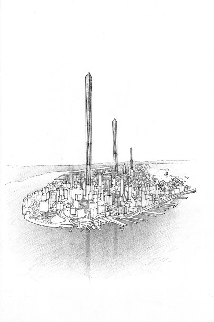
Mile-high
skyscrapers
Very tall buildings are unique environments that relieve the demand on
ground surfaces while increasing the stresses on the surface and the
infrastructure. The practicality of tall
structures is not a structural one but rather a spatial one and a matter of
public policy. The tops are well suited
for telecommunications, entertainment and tourism, and the lower levels for
human activities. The notion of the Horizontal
Skyscrapersm fragments the
building mass and provides access to light, air and visual vistas.
The author, John Mclean, RA, is the Principal
Architect and Designer for John Mclean Architect /
architecture & industrial design, White Plains, New York.
©
2013 John Mclean, RA. All rights reserved.